“It’s not what you tell them. It’s what they hear.”
Red Auerbach.
.
Ensure you clearly define your terminologies before starting on an OSS project.
As an overarching solution, the OSS will consolidate the management of business units, networks, technologies, processes and vendors. This consolidated management will introduce the need for identifiers that are unique across the entire organisation rather than within sub-sections of the organisation (ie global uniqueness versus local uniqueness). Prior to the OSS, it was possible for two separate business units to manage a device named ABC001 in isolation of each other, but under an OSS each of these two devices need to be identified separately.
But before an organisation can develop an enterprise-wide naming convention they must clearly define the terminology present throughout their organisation. It is likely that there will be terminology inconsistencies throughout the organisation and further mismatches of terminology with the vendors / integrators.
For example, there are mismatches in common industry-wide terminology such as what constitutes a “circuit.” The diagram below shows one example of a terminology map, but this definition exercise must be undertaken by each Organisation.
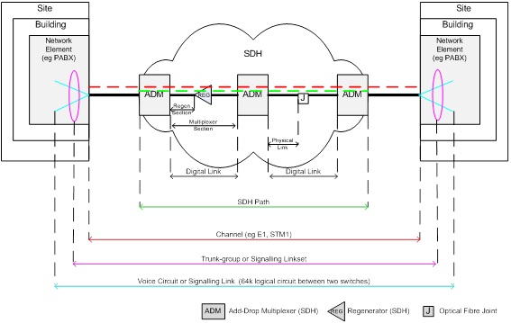
This diagram above is used to show the difference between each interchangeable use of the term “circuit,” also identifying that there can be multiple layers in a circuit hierarchy.
It should be noted that some OSS collectively represent all of the coloured layers in the diagram above as a single entity called a circuit, but use functionality within the application to represent the circuit hierarchies.
Physical Link: represent the physical segments of the network, including cables, point-to-point radio links, etc
Digital Link: connection between two adjacent Add-Drop Multiplexers (ADMs) within the “transmission” domain.
Path or SDH Path: end-to-end connection through the transmission cloud. This is the “circuit” or path known within the transmission domain and has a bandwidth of VC12, etc.
Channel: connection between two adjacent PABXs or other end devices, generally an Ethernet, E1 or STM1 in the Organisation’s network. This is nominally just an extension of the Path mentioned above, but represents the connection between end devices rather than transmission termination points. The channel may have a bandwidth of E1 that is encapsulated within the VC12 of the Path mentioned above. Since a channel crosses between domains (eg voice switching domain of the PABX to transmission domain), end-to-end data will not be captured within each domain’s NMS/EMS. The OSS will be responsible for finding linking keys between each domain’s data sets to establish an end-to-end view of this channel. This construct is most commonly referred to as a circuit.
Voice Circuit: 64 kbits/s connection between two adjacent switches supporting voice/PCM traffic (carried between switches by the “channels”). Note that since voice circuits are dynamically allocated during the establishment of a call, they won’t be tracked in the OSS and hence there is no need to establish a naming convention for these circuits. However, it is demonstrated here to show the different useage of “circuit” terminology that people use interchangeably and can be confusing
Signalling Link: 64 kbits/s connection between two adjacent switches supporting signalling traffic (carried between switches by the “channels”).
Trunk Group: Set of Voice Circuits defined locally to a switch. Trunk Group manages the Voice traffic towards one Signaling Point (Adjacent Switch).
SignallingLinkSet: Set of Signalling Links defined locally to a switch. SignallingLinkSets manage the signalling traffic towards one Signaling Point (Adjacent switch or STP).
Destination: is the final switching point (no concept of transit nodes or next hop because it is the final switching point only).
Route: is a path out of a given switch. It may consist of a single trunk group, or in the case of load-sharing and/or prioritisation, may consist of multiple trunk groups. In addition to this, there may actually be multiple routes to a single destination (primary route, secondary, etc).
Location: is a place where the Organisation’s communications equipment exists. There many ways that this can be represented. This may be a site, building, room, a functional group if they share a building but the Organisation wishes to represent them as separate items in the database (eg perhaps MSPs [Maintenance Service Providers]). A building may even be used to designate external plant entities (eg tower, cabinet, fibre tee, enclosure, pit / manhole, etc) if the OSS doesn’t have the ability to model Containers or similar.
Packet switched data networks: The world of the packet-switched network is evolving rapidly in terms of new protocols and delivery mechanisms. Being dynamically switched, there is no nailed-up path through the network like there was with PDH, SDH and others. This can cause concern for some OSS that rely on circuit-oriented connections to be modelled through a network. Virtual Paths (VP), Virtual Circuits (VC), Permanent Virtual Circuits (PVC), Label-Switched Paths (LSP) and other similar constructs can be used to mimic “circuits” in an OSS.
Other terminology inconsistencies relate to services and products, with the sales department often having different meanings for these terms than the network engineers.
To further agitate the terminology soup, as indicated in OSS History / Standards, there are no strict boundaries pertaining to the various management frameworks, meaning that each vendor can claim conformance with each standard.
For example, the developer of an OSS application with functionality that largely resides within the definition of the Service Management Layer can communicate directly with network devices and offer functionality commonly provided within the Element Management Layer. In this case, the vendor’s tool actually performs functionality of three layers of the TMN model.