

The Age-Old IT vs OT Debate: Who gets the Keys to Your OSS?
For decades, organisations have argued over whether IT or operations (OT) teams should control the OSS environment, as though it’s a binary decision. Giving one
Since we’re on the train of root-cause this week (see the 4 RCA proximity techniques article), I thought I’d share a root-cause technique that relies on topology proximity. It’s referred to as Root Cause Trace (RCT).
Many of our networks (eg access networks like FTTx, mobile, HFC, etc) are tree or bus in nature, whether that’s in the physical, logical or virtual / hierarchical sense. As such, that makes them well suited to modelling in graph databases. It was common for network traces (eg tracing up the tree from NTD #1 to Pillar #1 in the example below) to take long periods in the past [That was because the relational databases that were traditionally used needed multi-table joins on tables with lots of records, which required lots of compute]. It tends to be much more efficient with the graph databases we use today.
The RCT technique I’ll describe today makes use of those graphs.
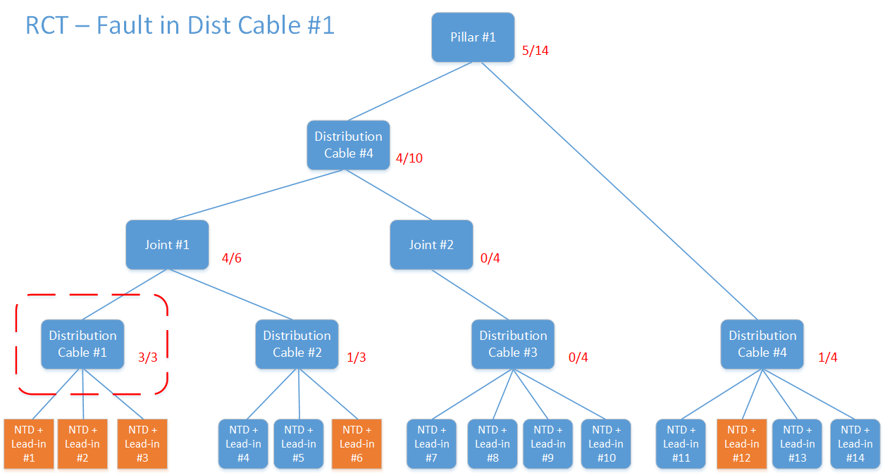
In the three examples below, you’ll notice that I’ve used passive inventory (pillars, cables, joints). These device types can’t send alarms. Only the NTDs can send alarms. The NTDs marked in orange indicate they are currently in an alarmed state. So if the passive devices can’t send alarms, how can we determine if any of them are the root-cause of a fault.
Let’s start with the example where there’s a fault with distribution cable #1. Perhaps it’s been cut by an excavator. As we can see, all of the NTDs downstream of Dist Cable #1 are impacted (in orange). Therefore, if we trace up from each of the NTDs in this graph to the pillar, we can see that the circled cable is on 3 of 3 trace-up paths. That’s the common point of failure. You’ll also notice that NTDs #6 and #12 are also alarmed, but they appear to be unrelated. This allows us to create a new fault (relating to Dist Cable #1), associate alarms from NTD #1, #2 and #3 to the fault, but also suppress those NTD alarms (but not NTD #6 or #12).
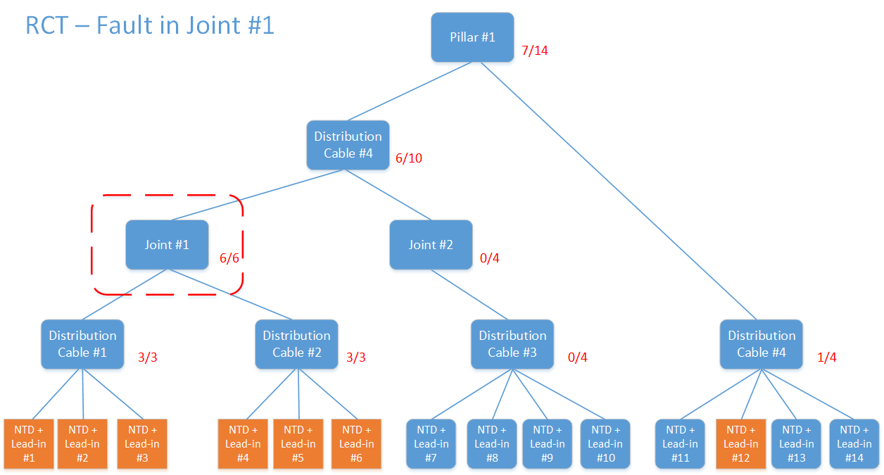
The scenario below shows an example where Joint #1 is impacted. Perhaps a car has hit a pole that it was attached to, causing damage to the joint. Therefore, all NTDs downstream of the joint will be in an alarmed state. If we perform the same set of trace-ups, we find that Joint #1 is the common point (all 6 of 6 downstream NTDs are alarmed).
Now, if we look at the scenario below, pillar #1 has been damaged. Perhaps it was directly hit by a car. All NTDs downstream of it are alarmed. The trace-ups all combine at Pillar #1 (14 of 14 downstream NTDs are alarmed). We create a fault on the pillar and attach, then suppress all the NTD alarms.

Just one extra point to note here. It’s possible that NTDs #6 and #12 already had unrelated problems before the car hit the pillar. Repairing the pillar may remove that root-cause, but any suppressions need to be removed (from all NTDs) so that unrelated alarms from NTDs #6 and #12 can be picked up.

For decades, organisations have argued over whether IT or operations (OT) teams should control the OSS environment, as though it’s a binary decision. Giving one
Given the topical theme of the World Cup final, we’ll go with a soccer story today. For the World Cup final, do you think Argentina
For decades, scale gave large telcos purchasing power, infrastructure reach, extensive capability and millions of customers. It became one of the world’s most powerful and

Success in business, distilled to its simplest form, is often about arbitrage. The gap between supply and demand. The gap between value delivered and value