Trust
We speak with buyers and sellers every week, and one word keeps repeating. Trust. It keeps appearing in buyer conversations and seller conversations alike. It’s
This article provides a tutorial for building a Power network with corresponding SCADA and comms network into the inventory module of our Personal OSS Sandpit Project.
This prototype includes components such as:
We’ve modelled the network on a small sub-section (circled in yellow) of the Terna network based on a network map shown in this link. Other than the high-level links shown in the diagram below, the rest of what’s modelled below is all hypothetical as we have no direct involvement with the Terna network.

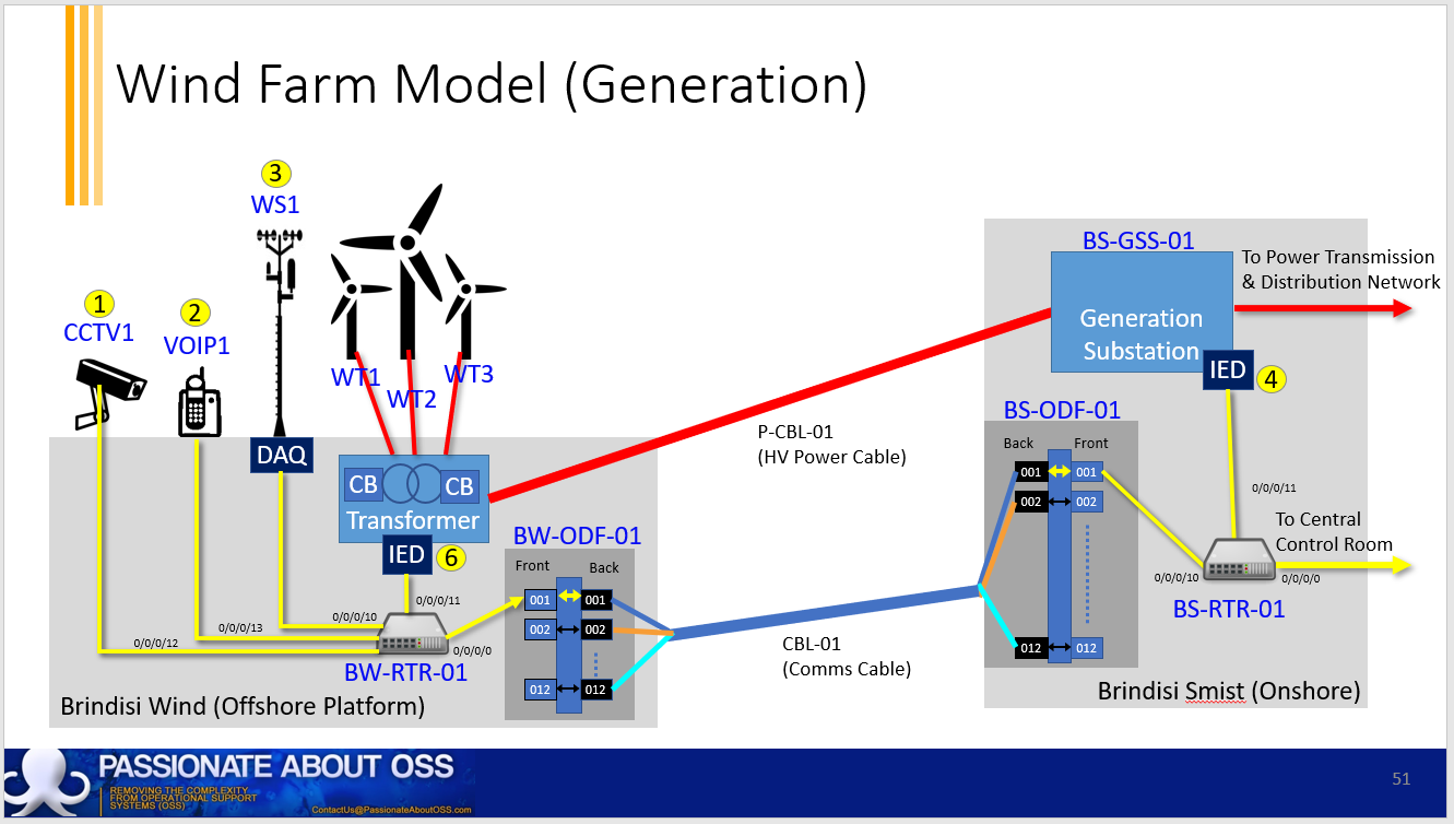
We’ve modelled two off-shore windfarms, with the diagram below showing one of the off-shore platforms.

You’ll notice that there are two separate networks shown. The power network (in red) and the comms / supervisory (in yellow).
As shown in the diagram below, we’ve also modelled the networks all the way back to:

Note that the yellow link above between towers TW-01 and TW-02 show the use of OPGW cables, which could be considered to represent both power (protective groundwire) and comms (optical fibres) networks.
Device Instances
First we start by building the locations and hierarchy of devices within them in Kuwaiba. The diagram below shows the new devices we’ve built to support this model:

The tree is only partially expanded. You’ll notice how these assets align with the conceptual diagrams above.
Applications
There are many applications required to manage these overlapping networks, as shown on Private Cloud Hosting below

Meteorological Masts / Weather Station
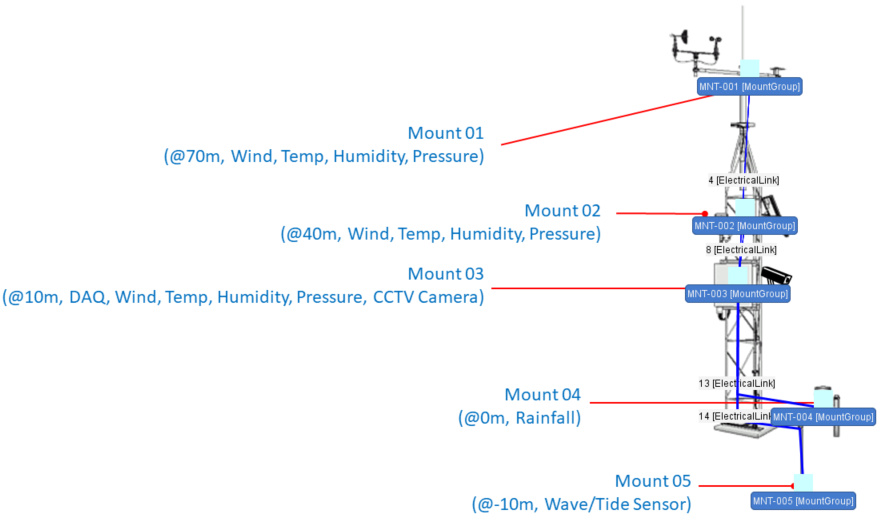
We’ve modelled the Met Masts in Kuwaiba, where the following shows an image (set up as a background bitmap), overlaid with Mount Groups and connectivity within Kuwaiba’s Object View functionality.

The Mount Groups on this mast are loaded into Kuwaiba with weather sensors at different heights, as seen in the diagram below:

You’ll notice that the last 6 ports on the Data Acquisition device (DAQ) remain unused.
Connectivity
Next, we have to model the connectivity. This includes three levels of connectivity – inter-site cabling, intra-site patching and then end-to-end connectivity.
We’ll start with the inter-site cabling in Kuwaiba’s OSP View:

Blue lines are the optical fibre cables and red represent the power links from the Wind Turbines to their off-shore platforms.
The following diagram takes a closer look at the power cables, both from the transformer on the off-shore platform, through to transmission, distribution and even lead-in cables to local residences:

The diagram below shows some local lead-in cables

Once all the intra-site connectivity has been created, we can see the topological view, which is almost identical to the first image above:

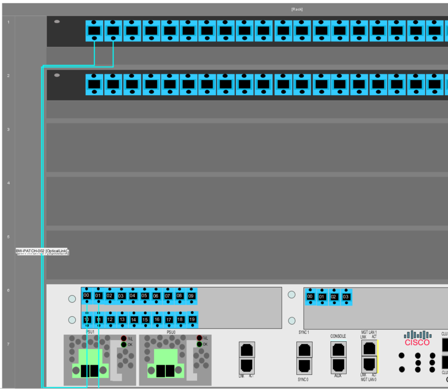
Intra-site connectivity, such as patching at the ODFs (Optical Distribution Frames), splicing and cable management allows us to build end-to-end connectivity. The diagram below shows a snippet of the rack layout view on the off-shore platform at Brindisi Wind Farm:

The diagram below shows how we manage the OPGW cable strung between towers TW-01 and TW-02. You’ll notice the “power ports” as well as the optical fibre tubes / strands:

Note that the “power port” naming used here could be misleading. Given that the groundwire is used to protect other conductors on the tower from lightning strikes, it doesn’t actually carry power as such. It’s also not a port, but the termination of a conductor. Power ports are part of the base Kuwaiba data model, probably intended to represent the power plugs on active equipment like modems and switches. We’ve simply re-purposed them to show connectivity of power cables and groundwires.
Now that we’ve created the connectivity, we can perform end-to-end tracing to ensure they’re properly connected.
First we’ll trace the power tree from the Generation Sub-Station at Brindisi Smist:

You’ll notice that there are four homes highlighted, where customer C-0001 has additional microgeneration infrastructure and is supplying power back to the grid through an inverter.
Next, we trace the comms / supervisory network, which is more extensive:

Numbers 1 to 6 have been added manually to the screenshot to correspond to the end-points highlighted in yellow on the second and third diagrams above.
And finally, we’ll trace the resilient link from the Brindisi Wind Farm via CBL-02 (as opposed to the main cable CBL-01 that’s used to trace the other circuits above):
Double-click to take a closer look.
Customer Service Mappings
We’ve shown examples of how to map services and calculate service impact in our other earlier tutorials so we won’t cover these again here.
Summary
The demonstrated tool can be used for modelling any form of infrastructure (ie comms, power, water, IoT / sensors, etc). Just like an asset management system, but also showing all the connectivity and their geo-spatial position as well as services/customer mappings. It’s far better as a design and ongoing infra management tool than CAD drawings that are traditionally used.
I hope you enjoyed this introduction into how we’ve modelled sample overlapping power / comms / supervisory networks into the Inventory module of our Personal OSS Sandpit Project. Click on the link to step back to the parent page and see what other modules and/or use-cases are available for review.
A Few Caveats
Acknowledgements regarding modelling limitations above:
If you think there are better ways of modelling this network, if I’ve missed some of the nuances or practicalities, I’d love to hear your feedback. Leave us a note in the contact form below.

We speak with buyers and sellers every week, and one word keeps repeating. Trust. It keeps appearing in buyer conversations and seller conversations alike. It’s

The promise is simple: let AI handle the easy work, and humans focus on the hard work, the challenging work, the fun work. But the

I’d always assumed that more feedback loops meant better control, and faster / smarter / optimal operations. But what happens when each system has its

We’re already seeing it. AI is slowly infiltrating telecom, one little project at a time… monitoring, automating, optimising. In AI, we have one of the