

For the World Cup Final, will You replace Messi with a Local Club Player to lower wage costs?
Given the topical theme of the World Cup final, we’ll go with a soccer story today. For the World Cup final, do you think Argentina
A regular reader of the PAOSS blog recently wrote, “I follow with passion your blog,latest post about Inventory are great [Ed. the reader is talking about this post about LNI and PNI and this one about Inventory vs Asset vs CMDB Management]. I ask you if possible have a post on Inside Plant vs Outside Plant vs Virtual network creation… we usually use CAD based tool for Inside Plant design both for TLC equipment, cabling, cross connection, Distribution Frame, rooms, virtual rooms, rows structure,etc but also for power, conditioning, lighfiring,etc. We also use Network Inventory for Datacenter and server farm modelling.Outside Plant typically deals with GIS tool for cabling infrastructure. And now also virtualizzation of Network is coming with NFV and SDN. What do you think about?”
Great question.
In the post about Inventory vs Asset vs CMDB, we used the following Venn Diagram:
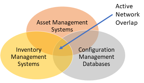
Unfortunately, there’s another circle that’s not shown on this diagram, but should be – the DCIM (Data Centre Infrastructure Management) circle. The overlaps between OSS and DCIM partially answer the questions above. We wrote a 5 part series on DCIM back in 2014 (part one, two, three, four, five), so perhaps it’s time for a re-visit.
The last of those five posts even included another Venn Diagram, as follows:

Data Centre Infrastructure Management (DCIM) shares much of its DNA with OSS, but also has a number of unique differences.
Similarities:
Differences (ie what Data Centres have that traditional CSP networks don’t):
So let’s now look at how it “might” all hang together (noting that each company is likely to be different depending on their systems and processes):
I can see that CAD might still be required for trayway, HVAC ducting, etc because PNI isn’t really designed with this in mind in 3D.
Having said that, I’d probably still attempt to get all connectivity and support designed into a spatial visualisation tool like PNI rather than CAD. Afterall, connectivity of any type can be modelled as nodes and arcs (same as PNI). It’s just that ducting tends to have a greater 3D heft than a single line / arc of a typical comms cable.
Why is it important to have this data in a single spatial system rather than CAD? Well, I figure it should help future augmented reality (AR) use-cases like the ones described in the link.
So here’s the updated diagram:

* There are of course multi-site DC organisations that have links between their sites, but they tend to outsource their long-haul network links to traditional carriers.

Given the topical theme of the World Cup final, we’ll go with a soccer story today. For the World Cup final, do you think Argentina
For decades, scale gave large telcos purchasing power, infrastructure reach, extensive capability and millions of customers. It became one of the world’s most powerful and

Success in business, distilled to its simplest form, is often about arbitrage. The gap between supply and demand. The gap between value delivered and value
When it comes to OSS, the term Out of the Box (or OOTB) can be correct, incorrect and highly confusing all at the same time.